|
|
|
input |
 The input sub menu on the right is accessed by holding down the third mouse
button and choosing the input item. From this sub menu you can open
windows that let you view and modify everything about baudline that is input
related.
The input sub menu on the right is accessed by holding down the third mouse
button and choosing the input item. From this sub menu you can open
windows that let you view and modify everything about baudline that is input
related.
Baudline can take signal data from many different places.
The input devices window controls the collection of streaming signal
data. Alternately, the open file window can be a static signal
source. From either input stage the signal flows into a large circular
capture buffer which feeds the channel mapping window. The channel
mapping window controls the data routing, operations, transforms, follow-on
processing, and color ramp selection. From here the data flow passes out
of the input module and directly into the signal processing and display
modules.
The diagram below illustrates this input signal flow.
|
|
|
|
input devices |
 The input devices window lets you enable and configure the input sources that
feed into baudline. Input sources can range from sound cards, USB
devices, standard input, and the tone generator loopback. Hardware
parameters such as sample rate, number of channels, mixer channel routing, and
mixer input gain can be modified. Also, baudline DSP parameters such as
decimation rate and input down mixing can be configured here.
The input devices window lets you enable and configure the input sources that
feed into baudline. Input sources can range from sound cards, USB
devices, standard input, and the tone generator loopback. Hardware
parameters such as sample rate, number of channels, mixer channel routing, and
mixer input gain can be modified. Also, baudline DSP parameters such as
decimation rate and input down mixing can be configured here.
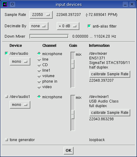
All the controls on this window can be changed in real-time, but changing the
sample rate, decimate by, device, or channel is destructive and will result in
a clearing of all internal sample buffers. This means any loaded or
recorded signals are going to be lost. Save any important signal data
before changing these settings.
 Sample Rate
The menu to the right is a list of the available sampling rates.
All the standard rates are supported; from 4000 to 192000 samples per
second. This is the global rate for all of baudline.
This sample rate is the value the audio card and/or the
stdin are set to.
The Nyquist sampling
theorem states that the highest frequency that can be accurately represented
is a frequency that is half of the sampling rate. So 22 kHz is the
highest frequency that is attainable at the sample rate of 44100 samples per
second. Note that the available sample rates vary from card to
card. For example, some modern cards can't support 48000 samples/sec and
some old audio cards can only support rates as high as 11025 or 22050.
Also some cards support a rate of 5512 instead of the standard 5510.
If you desire a custom sample rate that is not part of the standard list you
can use the -samplerate
command line option to specify it. Non integer rates can be specified
this way.
A sample rate correction value and PPM error
will be displayed to the right of the Sample Rate menu setting if the
calibration button has been pressed or if the
-calibratesr command line option is
set. The correction value can be cleared and reset to the native
requested sample rate by selecting a different rate. Using a corrected
sample rate value improves both time and frequency measurement accuracy.
PPM is a measurement of sample rate error and it can vary dramatically from
card to card, from sample rate to sample rate on the same card, and even
between half and full duplex
operation.
 Decimate By
The menu to the right is a list of the available
decimation ratios.
The decimation range is from none, 2, 4, all the way to 4096. Since
this value is a ratio it is unitless. The Decimate By value M reduces
a signals sample rate by a factor of M; this is known as downsampling.
Downsampling is as simple as reducing the amount of waveform data by taking
every Mth sample and discarding the rest. If you are only interested in
bass frequencies then downsampling is a very useful thing to do for these
three reasons.
- Downsampling has the effect of increasing the low frequency resolution,
which means more detail at the frequencies you are interested in.
- Downsampling reduces the sample rate, there is now less data to store and
process. This can reduce memory and CPU requirements.
- Downsampling increases the spectral SNR just as if a larger FFT size was
used.
So when downsampling, the effective sample rate, which is displayed in the
main window title bar, is the equation: sample rate divided by decimation
ratio. When decimating you have the option of down mixing. Also
note that decimation and down mixing can be done on both the input of audio
cards and on the standard input stream.
 Decimation Gain
Add from 0 to +90 dB of gain to increase the bits of precision when
decimating. This is useful for improving extraction and it works for
decimation and/or downmixing.
Increasing either the decimation factor or the FFT size pushes down the noise
floor which improves the spectral SNR. With decimation this works well
until baudline's internal 16-bit noise floor is reached. Use the
decimation gain feature to prevent this bit loss. Be cautious of too much
gain that can cause clipping.
A good rule to follow for weak signal extraction is +3 dB of decimation gain
for every doubling of the decimation factor. For example: +18 dB gain
when decimating by a factor of 64 unless strong signals are causing clipping.
anti-alias filter
Straight decimating without filtering will cause severe
aliasing for most real world
signals. This is bad. The anti-alias filter is a sharp low pass
filter (LPF) with its cutoff frequency slightly before the decimated sample
rate's new Nyquist frequency. In the stop band zone the attenuation is
-90 dB. This eliminates the aliasing.
For all normal decimation
usage the anti-alias filter should be set to ON; in the case of a Decimate By
value of "none" the filter is automatically disengaged. The anti-alias
filter toggle button is provided for educational and experimental
purposes. Turning the anti-alias filter to off will reduce the CPU load
slightly because the sharp low pass filter is an expensive operation, but in
relation to what the rest of baudline is doing CPU-wise, this filter's cost is
not that significant. So keep the anti-alias filter turned on unless you
are experimenting.

Down Mixer
The Down Mixer, also known as a Digital Down Converter
(DDC), is like a
heterodyne tuner. It takes a chunk of bandwidth, determined by the
decimation rate, and mixes it down to baseband (0 Hz). The default down
mixer setting is OFF which is the range of 0 Hz to the Nyquist frequency.
The width of the slider is determined by the decimation rate. Moving the
slider changes the upper and lower frequency range, note that the Hz axis in
the Spectrum and Average windows also changes. This can be thought of
like turning the frequency dial on a traditional radio.
The purpose of the down mixer is to zoom in (tune in) to a specific section
of bandwidth (frequency range). For an interesting example of the down
mixer see this Mystery Signal.
A 4000 sample per second rate with a 4096 decimation ratio was used to yield a
0.9766 sample per second rate that was tuned to a base frequency of 59.8144 Hz.
The diagram on the right describes how the down mixer works.
- A signal is multiplied by a complex sinusoid
- low pass filtered
- then decimated
The normal mode of operation for the down mixer is to take a
real signal as input, mix it down to baseband, and then output a real
signal. This behavior is changed if the
-quadrature command line option is
used. With a quadrature input, the signal pair is mixed down in
quadrature and the output is a quadrature signal. When a real
(mono) input is mixed down accompanying the -quadrature command line option
the output is quadrature (I/Q). With this method quadrature signals can
be created from real signals and even though the sampling rate is halved, no
information is lost.
Use the Left and Right arrow keys for fine adjustments to the down mixer
frequency.
 Device
Every device that can be selected
for input processing into baudline is shown here. The first audio device
will almost always be /dev/audio. If there is more than one audio card
the second card could be either /dev/audio1 or /dev/audio2 or something else
all together depending on the audio driver in the kernel. Note that changing
which devices are enabled will be destructive to any data currently
in baudline's sample buffers.
The menu on the right shows the current number of channels. This menu
tells baudline how many channels to enable for input collection and processing.
A channel can be either mono or stereo (1 or 2 channels) and this
changes with different mixer devices. Typically microphone inputs are
mono and CD inputs are stereo, but this is not always the case. A channel
that is stereo can have either the left, right, or both (stereo) channels
selected.
Channel
Choose from microphone, line, CD, synthesizer, phone in, and many other input
channel devices. Enabling the input channel setting does two
things. First of all, it is like choosing an input source in
a typical mixer application. That is like physically flipping a routing
switch in the audio chip that sends this particular channel to the analog
to digital converter (ADC). Second, it tells baudline how many channels
to enable (mono or stereo) in the channel menu described above. Note that
changing the channel options will be destructive to any data currently in
baudline's buffer.
 Gain
Gain
This single slider adjusts the mixer gain for the given input device.
Actually it is more complicated than that. Depending on the choice of
the input channel selected there are several different mixer channel gains
that are adjusted simultaneously.
The goal was to provide the user with just one slider gain control
that will work correctly. If you need separate channel controls for
stereo inputs, or if your mixer is really non-standard and it isn't working
the way you want, then run a separate mixer application and control the gain
from there; baudline will be perfectly happy with that. Note that
baudline will sense any mixer gain changes and adjust its own sliders in sync
just like the behavior of running "xmixer -poll."
Information
The /dev/mixer and the audio codec/mixer name will be displayed. Audio
cards are either half or full duplex,
and if the device is in use and can't be queried, then "unknown duplex" will
be reported. Half duplex means that a device can either be recording or
playing a signal, but not both at the same time. Note that many
soundcard drivers report erroneous half duplex values when in fact full duplex
operation is supported.
calibrate Sample Rate
Pressing the calibrate Sample Rate button sets the
sample rate correction value. Below the
calibrate button is the sample rate estimate that uses the main system clock to
track the true ADC sample rate. This value will improve in accuracy
and converge as the collection time increases. The sample rate estimate
value will turn red in color when a
potential drop happens. This loss
of sample fragment data invalidates the accuracy of the estimate. The
sample rate estimation values can be logged with the
-debugrate command line option.
For a further in depth analysis of this topic see the
sample rate stability app
note.
tone generator
The tone generator is a virtual loopback device for routing a
digital copy of the output from the tone generator. This is
useful if you are interested in monitoring the pure digital tone output
before it is corrupted by the digital to analog converter (DAC). Note
that if the tone generator is not currently running then zero silence will
be fed into the loopback until the tone generator is turned on.
stdin
Enable/disable standard input as the data stream input source. The
-stdin command line option must be set for
this device entry to be visible.
|
|
|
|
|